VEHICLE SPEED SENSOR (VSS)
Comprehensive Guide to Vehicle Speed Sensors (VSS): Function, Symptoms, and Diagnostics The Vehicle Speed Sensor (VSS) is a critical component in modern automotive engineering, serving as the sensory link between your vehicle’s mechanical movement and its electronic brain. This sensor monitors how fast your vehicle travels and relays this data to the onboard computer, also […]
Comprehensive Guide to Vehicle Speed Sensors (VSS): Function, Symptoms, and Diagnostics
The Vehicle Speed Sensor (VSS) is a critical component in modern automotive engineering, serving as the sensory link between your vehicle’s mechanical movement and its electronic brain. This sensor monitors how fast your vehicle travels and relays this data to the onboard computer, also known as the Powertrain Control Module (PCM) or Engine Control Unit (ECU).
This guide provides an in-depth look at the VSS, covering its working principles, common failure symptoms, and professional diagnostic procedures.
What is a Vehicle Speed Sensor (VSS)?
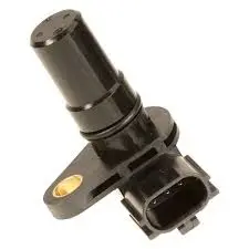
A VSS measures the rotational speed of a device typically the transmission output shaft or the differential gear and converts it into an electrical signal. The onboard computer utilizes this signal to modify engine functions, control transmission shift points, operate the speedometer, and manage cruise control.
While older vehicles relied on mechanical cables, modern systems use electronic sensors. These are usually mounted on the gearbox (transmission), tachometer, or wheel hubs (often integrated with ABS systems).
Types of Vehicle Speed Sensors
Automotive manufacturers utilize different technologies to measure speed. Understanding these types is essential for accurate diagnosis.
1. Hall Effect Sensors
This is the most common type found in modern vehicles. It operates by using a magnet and a Hall effect switch.
-
Power Source: Requires an external power supply (typically +12V from the ignition).
-
Signal Output: Generates a digital rectangular (square wave) signal. As the tachometer cable or gear rotates, the Hall switch turns on and off, creating a frequency that corresponds directly to vehicle speed.
-
Voltage: The signal typically toggles between 0V and 5V, or in some configurations, up to the battery nominal voltage.
2. Inductive Speed Sensors (Passive)
These are widely used in ABS systems and older transmissions.
-
Power Source: Does not require an external power source; it generates its own voltage.
-
Signal Output: Produces an analog sinusoidal (AC) signal.
-
Working Principle: A toothed wheel rotates past a magnetic coil, inducing an alternating current. The frequency and amplitude of the wave increase with wheel speed.
3. Mechanical Tenon / Reed Switch Sensors
Often found in hybrid mechanical-electronic setups.
-
Signal Output: Rectangular pulse form.
-
Characteristics: The signal voltage switches between 0V and +5V (or near battery voltage). The duty cycle of the pulses typically falls between 40% and 60%.
Symptoms of a Bad Vehicle Speed Sensor
A failing VSS can trigger a cascade of issues because multiple systems rely on its data. If you notice these signs, your sensor may be compromising vehicle safety and performance.
1. Malfunctioning Speedometer
The most obvious sign is a speedometer that behaves erratically, jumps between speeds, or rests at zero while driving. Since the VSS directly feeds the instrument cluster, signal interruption causes immediate display failure.
2. Transmission Shifting Issues
Automatic transmissions rely on speed data to determine when to shift gears. A faulty VSS can cause:
-
Hard shifting: Jerky or aggressive gear changes.
-
Delayed shifting: The engine revs high before the gear engages.
-
Limited gear operation: The car may refuse to shift into overdrive or higher gears.
3. Check Engine Light (P0500 Code)
When the ECU detects a loss of signal or erratic data from the VSS, it triggers the Check Engine Light. Common Diagnostic Trouble Codes (DTCs) associated with this failure include:
-
P0500: Vehicle Speed Sensor “A” Malfunction
-
P0501: Vehicle Speed Sensor “A” Range/Performance
-
P0502: Vehicle Speed Sensor “A” Circuit Low Input
4. Cruise Control Failure
Cruise control requires a steady speed signal to maintain velocity. If the VSS signal is unstable, the safety logic in the ECU will disable the cruise control system entirely.
5. ABS and Traction Control Issues
In vehicles where the VSS data is shared or derived from wheel speed sensors, a failure can illuminate the ABS or Traction Control warning lights, disabling these safety features.
Diagnostic Procedure: How to Test a VSS
Testing a VSS effectively requires a multimeter or, preferably, an oscilloscope to visualize the signal. The following procedure focuses on the common Hall Effect sensor.
/VSS.png)
Step 1: Visual Inspection
Before testing circuits, inspect the physical condition of the sensor.
-
Locate the VSS on the gearbox or transmission housing.
-
Check the connector for corrosion, loose pins, or broken wires.
-
Ensure the protective rubber muff is intact.
-
Verify the connector is firmly seated.
Step 2: Circuit Verification (Voltage and Ground)
-
Identify Terminals: Consult your vehicle’s wiring diagram to identify the Power (+), Ground (-), and Signal terminals.
-
Check Power: With the ignition ON (engine off), measure the voltage at the power terminal. It should be close to battery voltage (+12V).
-
Check Ground: Measure continuity between the ground terminal and the chassis. Resistance should be near zero.
Step 3: Signal Testing
To test the signal, the vehicle’s wheels must be turning.
-
Safety Note: Lift the vehicle securely on jack stands so the drive wheels can rotate freely.
-
Oscilloscope Setup: Connect the ground probe to the chassis and the active probe to the signal terminal of the VSS.
-
Generate Signal: Rotate the wheels by hand or gently accelerate the engine (if safe).
-
Observation: You should see a clean rectangular square wave.
-
Voltage Levels: The “high” part of the signal should reach roughly 8.8V to 10V (or 5V depending on the car).
-
Frequency: The frequency of the pulses must increase as the wheel speed increases.
-
Step 4: Troubleshooting “No Signal”
If you observe a flat line or constant voltage:
-
Disconnect the Sensor: Unplug the connector and turn the ignition ON.
-
Measure Signal Wire Voltage: Check the voltage on the harness side (coming from the computer). Some systems use a “pull-up” resistor, so you might see 5V or 12V on the signal wire even with the sensor unplugged.
-
Check Mechanical Drive: Remove the sensor and inspect the drive gear (pinion) inside the transmission. If the plastic gear is stripped, the sensor itself might be fine, but it isn’t being spun.
Conclusion
The Vehicle Speed Sensor is a small but pivotal component. While a failed VSS might seem like a minor annoyance such as a wobbly speedometer it can lead to severe transmission wear and safety hazards like ABS failure. Regular inspection of the sensor wiring and prompt attention to the P0500 code can save you from costly transmission repairs down the road.
If diagnostics confirm a faulty sensor, replacement is generally straightforward and affordable, restoring your vehicle’s performance and shifting quality immediately.
Related reading

Car Paint Shops near me
Your affordable car body shop You rely on your vehicle to get you from point A to point B. When unexpected damage or disrepair occurs, it is important to get in touch with an auto body repair shop that you can trust. The team of auto body repair specialists at fixmycar in Islamabad has been […]
honda
Best Suspension Parts at Fixmycar.pk
Why Are Suspension Parts Important for Your Vehicle? Best Suspension parts play a crucial role in ensuring a smooth, stable, and comfortable ride. A well-maintained suspension system helps: Absorb shocks from rough roads Improve handling and control Enhance overall driving comfort For vehicles like 4×4s, suspension becomes even more critical due to off-road demands. Why […]

5 Warning Signs Your Car Needs Immediate Wheel Alignment and Balancing
What is Wheel Alignment and Balancing? Wheel alignment is the process of adjusting the angles of your car’s wheels so they are perfectly aligned with each other and perpendicular to the road. This ensures smooth driving, even tire wear, and better fuel efficiency. Wheel balancing involves distributing the weight of the wheel and tire evenly. […]

mercedes
Importance of Pre-Purchase Inspections for Used Mercedes-Benz Vehicles
Introduction to Pre-Purchase Inspections for Used Mercedes-Benz Vehicles When considering buying a used Mercedes-Benz vehicle, conducting a pre-purchase inspection is a crucial step in ensuring the investment is worthwhile. This section will outline the importance of these inspections and what to expect when undergoing this process. By uncovering any hidden issues through a pre-purchase inspection, […]

honda
Honda Civic Turbo Transmission Failures
Honda Civic Turbo Transmission Failures: Questions and Answers What Is the Honda Civic Turbo? The Honda Civic Turbo is a modern version of Honda’s popular compact car equipped with a turbocharged engine designed to deliver better performance while maintaining fuel efficiency. Many recent Civic models use a 1.5-liter turbocharged engine that produces more power than […]

toyota
Toyota Raize in Pakistan: Price, Specs, and Variants
Toyota Raize in Pakistan: Price, Specs, Variants & Comparison with Daihatsu Rocky The Toyota Raize is making waves in Pakistan’s compact SUV market. With its head-turning design, fuel-efficient engine, and advanced features, the Raize has become a top choice for urban drivers looking for practicality combined with modern style. This article offers a comprehensive review of the Toyota […]